Posts

Showing posts from January, 2017

Free PCB Design CAD Software

Image
The ExpressPCB CAD software is very easy to learn and use. For the first time, designing circuit boards is simple for the beginner and efficient for the professional. Best of all, its FREE. Our electronics design software includes two applications, one for drawing schematics, the other for PCB layout. ExpressPCB ExpressSCH Both programs are completely free, fully functional and easily installed with a single InstallShield setup program. They run under Microsoft Windows NT, 2000, XP, Vista, Windows 7, 8.1 and Windows 10. Learning to use our software is fast because of its standardized Windows user interface. After spending the few minutes to learn one, the other takes almost no time because it works the same way. (Should you choose not to keep our software on your system, simply uninstall it using Add or Remove Programs found in your computer’s Control Panel.) Download ExpressPCB 7.3.4

220V AC Powered White Led Lamp

Image
This is the simple version of a white LED lamp that can be directly powered from mains. It can give ample light even for reading purpose. Capacitor CX along with diodes D1 through D4 forms the AC step down circuit. CX reduces high voltage AC from mains to a low voltage AC which is rectified by the diodes D1-D4. 220V AC Powered White Led Lamp Circuit Diagram Capacitor C1 removes ripples from AC so that low voltage DC is available to power the LEDs.CX is the X rated AC capacitor that reduces AC voltage through capacitive rectance property. Resistor R1 is very important to remove the stored voltage from CX when power is switched off. This prevents lethal shock. Resistor R2 limits the inrush current. More LEDs can be added by reducing the value of R2.Since the circuit is directly connected to mains, take utmost care to avoid shock. No components should be touched when it is connected to mains.

Electronic Alarm Project of Piezo with 555 Timer

Image
This is a very simple Electronic Circuit Project of piezo alarm circuit. Piezo alarm which will generate a sound around 110dB can be designed using this diagram. This Piezo alarm siren circuit diagram use some common components like 555 timer ic, you can use two 555 timer circuits or one 556 circuit. Electronic Alarm Project of Piezo with 555 Timer Circuit Diagram: This Piezo alarm siren circuit project use two piezo sounders with high efficiency and can be powered from a wide input voltage, between 5 and 15 volts. This circuit is very easy to build, maybe you will have a little trouble with the T1 and T2 auto-transformers. Both auto-transformers used in this project are the same type and require between pin 1and 2 1500 turns of 44 SWG wire and 220 turns between 2 an 3 using 40 SWgG wire. In this circuit the IC1:B closest to the piezo elements is set to oscillate around their resonant frequency. The frequency is then varied via input pin 11 from the other 555, IC1:A. This modulating in

Simple IR Remote Control Extender Circuit Diagram

Image
Description: An Infra Red wired Repeater circuit to control appliances from a remote location. IR Remote Control Extender Circuit Diagram Parts List: R1: 1k Resistor (1) R2: 3.3k Resistor (1) R3: 10k Resistor (1) R4: 15k Resistor (1) R5: 2k2 Resistor (1) R6: 470R Resistor (1) R7: 47R Resistor (1) 0.5 Watt PR1: 4.7k Preset (1) C1,C3: 47u Elect(2) C2: 1n Polyester 5% or better (1) C4: 100u Elect(1) Z1: 5V1 Zener (1) Q1: BC549C or BC109C or 2N2222 (1) Q2: BC337 or BC549 or ZTX450 (1) IC1 : TSOP1738 IC2: 555 or 7555 (1) LED1 5mm RED (1) LED2,3 IR diode TIL38 or similar (2) Alternatives to IC1 : Everlight IR receiver module ELIRM 8621 Harrison electronics IR1 Vishay TSOP 1838 Radio Shack 276-0137 Sony SBX 1620-12 Sharp GP1U271R Notes: The signal emitted by an IR remote control contains two parts, the control pulses and a modulated carrier wave. The control pulses are used to modulate the carrier, a popular modulation frequency being 36 and 42KHz. The signal is radiated by an IR diode, ty

Water Level Detector

Image
To monitor the filling of a bath, a water-tank, or a swimming pool, or to warn when a gully is overflowing, here’s a very simple water level detector built around a CD4011 CMOS quad NAND chip. Gates IC1.A and IC1.B are wired as an astable multivibrator. The oscillator frequency is determined by C1, R2 and preset P1. Water Level Detector Circuit Diagram : When quiescent, resistor R1 pulls the input to gate IC1.A down to logic low, which there-fore by default blocks the operation of the oscillator in the absence of water. When water is present between the e+ an d e−electrodes, IC1. A is taken high, enabling the oscillator. The output signal from gate IC1.B is shaped by IC1.C to obtain a rectangular waveform. Gate IC1.D inverts the signal so that transistor T1 is held of f in the absence of water, which avoids current flowing in the primary of transformer TR1 when the system is at rest. TR1 is a 12 V 1.5 VA AC power transformer wired as a step-up trans-former i.e. with the low-volt ag

STK4050 STK4046 Power Amplifier

Image
Amplifier circuit with IC STK is tough and good quality. In this article an amplifier circuit with IC STK another base. Power "Amplifier 200Watt By STK4050" is an audio amplifier of the STK family with 200Watt power. To create a power amplifier with the STK4050 IC is not require many external components. Power Amplifier uses symmetric 30Volt power supply system. Power Amplifier With this STK4050 can reproduce the power 200 Watts at 8 Ohm load spaker. In making Power Amplifier 200Watt With this STK4050 do not forget to provide adequate heat sink for the IC STK 4050 in order to avoid overheating. Schematics Amplifier STK4050-STK4046 PCB Layout Amplifier Series Power Supply for Power Amplifier 200Watt By STK4050 been displayed in one image with a series of "Power Amplifier" 200Watt With STK4050 above. IC STK 4050 in this series there are several types on the market including STK4050II, STK4050V and STK4050. And below is a list of STK ICs are used for a good quality amp

Hi Fi 25W Power Amplifier Class A

Image
Hi-Fi 25W Power Amplifier (Class-A) Schematics Circuit Click to view larger

Electronic Simple Project For Two Transistor AM Radio Receiver

Image
Here is simple Electronic Circuit Project of two transistor AM radio receiver circuit. This two transistor AM radio circuit is also called “mini-radio”. It uses only 2 transistors and few passive components which makes is very easy to be constructed. Although the circuit is very simple, it functions very well without external antenna or ground connection. The transistor T1 works as a feedback regulated HF-amplifier and function as demodulator at the same time. The sensitivity of the receiver is dependent on the amount of feedback and can be adjusted by P1. Two Transistor AM Radio Receiver Circuit Diagram: The demodulated signal comes out from the collector of T1. The signal is then filtered by C3 so that only the audio signal will be amplified by T2. The amplified signal is then delivered to a high impedance “earphone”. The coil is 65 turns AM antenna wire around a 10 cm long x 10 mm diameter ferrite rod. The tap is at the fifth turn of the coil counting from its ground end. The coil

Railway Points Sequencer

Image
Dedicated model rail enthusiasts using sophisticated train and points controllers often have the problem that as their layouts get bigger and more complex, the transformer supplying power to the points does not have enough current to switch several points at the same time. The actuators in the points are designed for ac operation so it doesn’t help by rectifying the supply and adding reservoir capacitors, the coils can overheat and burn out if they get jammed during their travel (ac operation actually helps to overcome friction in the mechanism). The circuit shown here solves this problem by using a sequencer to ensure than only one points actuator can be active at any point in time. During operation the controller will switch all the points on one line at the same time as usual, but the other connection to each coil is connected to the sequencer unit. This circuit will only allow current to flow through one coil at a time.  Railway Points Sequencer Circuit diagram : Railway Points Seq

Build 16 Stage Bi Directional LED Sequencer

Image
The bi-directional sequencer uses a 4 bit binary up/down counter (CD4516) and two "1 of 8 line decoders" (74HC138 or 74HCT138) to generate the popular "Night Rider" display. A Schmitt Trigger oscillator provides the clock signal for the counter and the rate can be adjusted with the 500K pot. Two additional Schmitt Trigger inverters are used as a SET/RESET latch to control the counting direction (up or down). Be sure to use the 74HC14 and not the 74HCT14, the 74HCT14 may not work due to the low TTL input trigger level. When the highest count is reached (1111) the low output at pin 7 sets the latch so that the UP/DOWN input to the counter goes low and causes the counter to begin decrementing.  When the lowest count is reached (0000) the latch is reset (high) so that the counter will begin incrementing on the next rising clock edge. The three lowest counter bits (Q0, Q1, Q2) are connected to both decoders in parallel and the highest bit Q3 is used to select the appropr

Relay activated by Sound Circuit Diagram

Image
This is a Relay activated by Sound Circuit Diagram . Generally a circuit has a basic function, but according to our needs can modify or add to a circuit making it more complex. This circuit is a relay activated by sound, which can be used in an alarm system, home automation, robot and even in an Arduino. Undoubtedly this control by sound can be very useful, an example is a light activated by the sound of a knock on the door or a round of applause. The light turns off automatically after a few seconds. An alternative is to use protection against theft - if someone wants to open the door or break something light illuminates, indicating that someone is home. The circuit can work with any voltage 5-12 Vdc, it depends on the voltage of the relay coil. Relay activated by Sound Circuit Diagram

Simple Regulated 12 Volt Supply

Image
Quickly find a reliable and cost effective a simple regulated 12 Volt power supply  Notes: This circuit above uses a 13 volt zener diode, D2 which provides the voltage regulation. Approximately 0.7 Volts are dropped across the transistors b-e junction, leaving a higher current 12.3 Volt output supply. This circuit can supply loads of up to 500 mA. This circuit is also known as an amplified zen-er circuit .  

Peak Indicator Circuit

Image
How to build a peak indicator circuit . Each time where the level of signal exceeds the level + 4dB, turns on led D1. It is useful in each channel of console of sound, in final amplifiers or in that other application, to we needed. With the prices of circuit, the indicate begins with levels above + 4 dB (1.25V rms). For adaptation in different levels of signal, we can use a trimmer, before capacitor C1. Parts: R1 = 10K R2 = 1.2K R3 = 220K R4 = 4.7K R5 = 4.7K C1 = 47uF-25V C2 = 2.2uF-25V Q1 = BC550C Q2 = BC550C D1 = Red LED Notes: It can be assembled on a general purpose PCB. It can be powered from a 12V-15V regulated power supply.

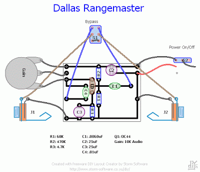
Dallas Rangemaster another layout

Image

Gambar Skema Rangkaian Subwoofer Filter Mobil

Image
Gambar Skema Rangkaian Subwoofer Filter Mobil The circuit is designed around the TL072 dual BIFET opamp IC. Out of the two opamps inside the chip, IC1A is wired as a buffer. The left & right audio inputs after mixing is fed to the input of the IC1A using the DPDT switch S1. Switch S1 is the phase control switch which can be used to make the subwoofer in phase with other speakers. When S1 is in position 2, 180 degree phase shift will be induced.POT R7 can be used for controlling the level. IC1B forms the low pass filter whose pass frequency can be controlled by adjusting the dual gang POT R13. Here is the circuit diagram of a simple subwoofer filter that can be operated from a 12V DC supply. Such a circuit is useful in automobile subwoofer applications. The circuit is nothing but a low pass filter whose pass frequency can be adjusted between 60 to 160 Hz.

Crowther Hotcake 1977 2003 Versions

Image

Automatic Water Level Sensor Pump Driver

Image
The circuit is based on a 555 IC (Bipolar or CMOS) for sensing the minimum and maximum water levels and turns a MOSFET on/off which directly controls a 12V DC pump motor. Or, it can power a relay coil to switch high currents/voltages, DC or AC. ‘Trigger’ and ‘Threshold’ pins (2 & 6) are used to detect the maximum and minimum levels, respectively. The two voltage comparator op-amps inside the 555 control the output, turning it on/off. Looking at the circuit diagram you will notice that the ‘Trigger’ pin (2) is marked ‘HIGH probe’, despite being triggered (output goes HIGH) when the voltage drops below 1/3 of the supply voltage and, the ‘Threshold’ pin (6) is marked ‘LOW probe’ while it is ‘reset’ (output goes LOW) when the voltage rises above 2/3 of the supply voltage. The circuit works as follows: Three (3) probes are immersed in the vessel. (usually from the top) One is the ‘GROUND’ probe, going to the level a little lower than the minimum desired level. This is the ‘common’ (or ‘

Under voltage indicator Circuit Diagram

Image
Under voltage indicator Circuit Diagram as use for battery equipment . This is a meter counter circuit in this circuit due to the low duty cycle of flashing LED, the average current drain is 1 mA or less. The NE555 will trigger the LED on when the monitored voltage falls to 12 volts The ratio of Rl to R2 only needs to he changed if it is desired to change the voltage point at which the LED is triggered. Under voltage indicator Circuit Diagram Sourcd By : Circuitsstream

ESR and Low Resistance Test Meter Circuit Diagram

Image
This is a simple project of ESR and Low Resistance Test Meter Circuit Diagram. As electrolytic capacitors age, their internal resistance, also known as "equivalent series resistance" (ESR), gradually increases. This can eventually lead to equipment failure. Using this design, you can measure the ESR of suspect capacitors as well as other small resistances. Basically, the circuit generates a low-voltage 100kHz test signal, which is applied to the capacitor via a pair of probes. An op amp then amplifies the voltage dropped across the capacitor’s series resistance and this can be displayed on a standard multimeter. In more detail, inverter IC1d is configured as a 200kHz oscillator. Its output drives a 4027 J-K flipflop, which divides the oscillator signal in half to ensure an equal mark/space ratio. Two elements of a 4066 quad bilateral switch (IC3c & IC3d) are alternately switched on by the complementary outputs of the J-K flipflop. One switch input (pin 11) is connected to

Simple 40 LED Bicycle Light

Image
How to build a 40 LED Bicycle Light Electronic circuit Project? This is a very Simple to build This electronic circuit project of 40 LED bicycle light.  The 555 circuit below is a flashing bicycle light powered with four C,D or AA cells (6 volts). Two sets of 20 LEDs will alternately flash at approximately 4.7 cycles per second using RC values shown (4.7K for R1, 150K for R2 and a 1uF capacitor). Time intervals for the two lamps are about 107 milliseconds (T1, upper LEDs) and 104 milliseconds (T2 lower LEDs). Two transistors are used to provide additional current beyond the 200 mA limit of the 555 timer. Simple 40 LED Bicycle Light Circuit Diagram : A single LED is placed in series with the base of the PNP transistor so that the lower 20 LEDs turn off when the 555 output goes high during the T1 time interval. The high output level of the 555 timer is 1.7 volts less than the supply voltage. Adding the LED increases the forward voltage required for the PNP transistor to about 2.7 volts

Bringing Theater Quality Sound Home

If you are one of the many people around the world who loves the sound quality of watching movies in theaters but hates the hassles (crying babies, people talking, cell phones ringing, etc) of actually going then I hope you are seriously contemplating the value that a home theater or surround sound system could bring to your movie enjoyment.  In fact, a good surround sound system cannot only improve your overall enjoyment of blockbuster hits but also your favorite music and video games as well. Surround sound is far more than a tool for watching movies at home, it is an entirely new way to look at and listen to your television in general.  You do not have to begin your home theater or surround sound experience with a top of the line piece of equipment. It is quite possible to start small with a surround sound system and build a better system as you go. In fact, I seriously recommend that people invest heavily in speakers from the beginning and sacrifice the number of speakers in favor

5W power amplifier with IC TDA1016

Image
This circuit use IC TDA1016 , minimum require voltage for this circuit 3 volt and maximum require voltage 15 volt .Its mono 5 Watt power output with impedance 4 Ohm , Current required 14 mA. In order for this circuit work optimally , the voltage should be at least 9 volts and the speakers should be higher 4 Ohm or equivalent, and use the speaker woofer. See Amplifier circuit schematic below :

Precision Headphone Amplifier Circuit Diagram

Image
Designs for good-quality headphone amplifiers abound, but this one has a few special features that make it stand out from the crowd. We start with a reasonably conventional input stage in the form of a differential amplifier constructed from dual FET T2/T3. A particular point here is that in the drain of T3, where the amplified signal appears, we do not have a conventional current source or a simple resistor. T1 does indeed form a current source, but the signal is coupled out to the base of T5 not from the drain of T3 but from the source of T1. Notwithstanding the action of the current source this is a low impedance point for AC signals in the differential amplifier. Precision Headphone Amplifier Circuit diagram: Precision Headphone Amplifier Circuit Diagram Measurements show that this trick by itself results in a reduction in harmonic distortion to considerably less than –80 dB (much less than 0.01 %) at 1 kHz. T5 is connected as an emitter follower and provides a low impedance drive

Video Isolator Circuit Diagram

Image
These days many more audio-visual devices in the home are connected together. This is especially the case with the TV, which may be connected to a DVD player, a hard disk recorder, a surround-sound receiver and often a PC as well. This often creates a problem when earth loops are created in the shielding of the video cables, which may cause hum and other interference.   . The surround-sound receiver contains a tuner that takes its signal from a central aerial distribution system. The TV is also connected to this and it’s highly likely that the PC has a TV-card, which again is connected to the same system. On top of this, there are many analogue connections between these devices, such as audio cables. The usual result of this is that there will be a hum in the audio installation, but in some cases you may also see interference on the TV screen. . The ground loop problem can be overcome by galvanically isolating the video connections, for example at the aerial inputs of the surround-soun

30 Watt x 2 CH AUDIO POWER AMPLIFER

Image
TA8233H Circuit Diagram Circuit diagram for 30 Watt x 2 CH AUDIO POWER AMPLIFER

22 Watt Car Subwoofer Amplifier Circuit Diagram

Image
This is a project of 22 Watt Car Subwoofer Amplifier Circuit Diagram. 22W into 4 Ohm power amplifier, Variable Low Pass Frequency: 70 – 150Hz . This unit is intended to be connected to an existing car stereo amplifier, adding the often required extra "punch" to the music by driving a subwoofer. As very low frequencies are omnidirectional, a single amplifier is necessary to drive this dedicated loudspeaker. The power amplifier used is a good and cheap BTL (Bridge Tied Load) 13 pin IC made by Philips (now NXP Semiconductors) requiring a very low parts count and capable of delivering about 22W into a 4 Ohm load at the standard car battery voltage of 14.4V. . 22 Watt Car Subwoofer Amplifier Circuit Diagram 22 Watt Car Subwoofer Amplifier Circuit Diagram Parts: P1_____________10K Log Potentiometer P2_____________22K Dual gang Linear Potentiometer R1,R4___________1K 1/4W Resistors R2,R3,R5,R6____10K 1/4W Resistors R7,R8_________100K 1/4W Resistors R9,R10,R13_____47K 1/4W Resistors

Classification of Oscillators

Classification of Oscillators The oscillators can be classified in the following ways. 1.        According to the generated waveform.            (a)      Sine wave oscillation            (b)      Relaxation or non-sinusoidal oscillators. 2.        According to the fundamental mechanism involved            (a)      Feedback oscillators            (b)      Negative resistance oscillators. 3.        According to the associated circuit components            (a)      RC oscillators            (b)      LC oscillators            (c)      Crystal oscillators 4.        According to the frequency range            (a)      Audio frequency (AF) oscillators             (b)      Radio frequency (RF) oscillators            (c)      VHF or microwave oscillators.

Balancing LiPo Cells Circuit project

Image
This is the Balancing LiPo Cells Circuit project. Things change fast in the electronics world, and that’s also true for recharge- able batteries. The rate of development of new types of rechargeable batteries has been accelerated by the steadily increasing miniaturisation of electronic equipment. LiPo cells have conquered the market in a relatively short time. Their price and availability have now reached a level that makes them attractive for use in DIY circuits. Unlike its competitors Elektor Electronics has already published several articles about the advantages and disadvantages of LiPo batteries. One of the somewhat less well-known properties of this type of rechargeable battery is that the cells must be regularly ‘balanced’ if they are connected in series. This is because no two cells are exactly the same, and they may not all have the same temperature. For instance, consider a battery consisting of a block of three cells. In this case the outer cells will cool faster than the ce

coaxial cable

Image

Simple F and V Converter Circuit Diagram

Image
This is a best Frequency/Voltage Converter circuit diagram proportional voltage by the use of a frequency-to-voltage (F/V) converter . Teledyne Semiconductor`s Type TSC9402 is a versatile IC. Not only can it convert voltage into frequency, but also frequency into voltage. It is thus eminently suitable for use in an add-on unit for measuring frequencies with a multimeter.   Best F and V Converter Circuit Diagram Only a few additional components are required for this.. Just one calibration point sets the center of the measuring range (or of that part of the range that is used most frequently). The frequency-proportional direct voltage at the output (pin 12—amp out) contains interference pulses at levels up to 0.7 V. If these have an adverse effect on the multimeter, they can be suppressed with the aid of a simple RC network.  The output voltage, U0, is calculated by: tfo=C/rei(Ci + 12 pF) R2fm Because the internal capacitance often has a greater value than the 12 pF taken here, the f

KLR250 Torque Specs and Other Information

Image
If you work on your bike yourself it is guaranteed that at some point you will be looking for torque specs for it. Thats usually a problem because the only place to get those numbers are from a factory service manual. Thats why we created this page, a one stop spot for torque specifications and other general information for the Kawasaki KLR250 dual sport motorcycle. Alternator Output: 10.5A @ 8,000 rpm - 14v Axle Nut Torque -Front: 58 ft/lb -Rear: 69 ft/lb Brake Drum Inside Diameter: 120-120.14mm (service limit 120.75mm) Brake Fluid Grade: DOT 3 or 4 Brake Pad Lining Thickness: 4.5mm (service limit 1mm) Brake Pedal Free Play: 0-1.2" (0-30mm) Brake Rotor Thickness: 2.8-3.1mm (service limit 2.5mm) Brake Rotor Run Out: Less tahn 0.15mm (service limit .3mm) Camshaft Bearing Inside Diameter: 23-23.013mm (service limit 23.07mm) Camshaft Bearing Oil Clearance: 0.045-0.073mm (service limit 0.16mm) Camshaft Chain Length: 20 link - 127-127.36mm (service limit 128.9mm) Camshaft Journal Diame

Mcu based inverter control with A V R using pic16f876a

Image
Monitoring of an inverter during operation has being the major challenge faced by local inverter Manufacture which has lead to low demand for locally built Inverters due to sudden break down or Battery being overcharged. most of the Inverter schematic claimed or used by Local Inverter Manufacture downloaded from the internet are for tutorial purpose not not for commercial there are tendencies for failure therefore it is time for us to start developing things of our own... proudly NIGERIA...... The featuring M.C.U is the Microchip PIC16F876A FEATURES OF THE ABOVE SCHEMATIC ARE STATED BELOW : INVERTER PROTECTION : LOW-BATTERY SHUTDOWN                                              : OVER LOAD SHUTDOWN INPUT                                              : O/P SHORT CCT SHUT-DOWN INPUT                                              : HIGH TEMPERATURE SHUT-DOWN INPUT                                              : LOW-BATTERY : BEEP START AT 11 V                                              :INVE