Posts

Simple 8 Channel DTMF Link Encoder

Image
Generated millions of times every day by our telephone keypads, the eight DTMF frequencies were chosen so that the harmonics and intermodulation do not generate significant in-band signal levels. The signal is encoded as a pair of sine waves, ensuring that no frequency is a multiple of the other and the sum and difference between two frequencies does not match any single tone and that’s why DTMF sounds so ugly!T he DTMF encoder circuit show n here is based on the HT9200B tone generator device produced by Holtek and distributed by Futurlec  among others. The encoder is complemented by a decoder elsew her e in this publication. 8-Channel DTMF : Encoder Schematic The HT2900B is supplied as a nice old fashioned 14-pin device. It can be instructed by a microcontroller to generate 16 dual tones and (in serial mode only) 8 single tones from the DTMF pin output . It s 8 - pin ‘ younger brother’ the HT9200A provides a serial mode only whereas the HT9200B contains a select-able serial/parallel m

Simple Auto Tachometer Circuit Diagram

Image
This is the Simple Auto Tachometer Circuit Diagram. Anyone performing their own automobile tune-ups knows how important it is to know your engines speed. With this tachometer, you can measure your engines speed without any connections or annoying timing lights.   Simple Auto Tachometer Circuit Diagram  PC board layout and parts placement Notes Calibrate the unit as folows: a.    Set up this circuit:    Turn on the Tach and allow a few minutes for temperature stabilization. Set S2 to 4 cylinders and adjust R5 for a meter indication of 180 (1800 rpm). Set S2 to 6 cylinders and adjust R6 for a meter indication of 120 (1200 rpm). Set S2 to 8 cylinders and adjust R7 for a meter indication of 90 (900 rpm). To use the Tach, turn it on and let it sit for one minute to allow for temperature stabilization. Extend the antenna, select the right number of cylinders and hold the unit over the engine. If the reading is erratic or the needle jumps around, move the antenna closer to the ignition coil o

1 6 Watt intregated circuit audio amplifier

Image
This Circut based on IC TDA7231 , Minimum voltage require 2 Volts and maximum voltage 15 volts . I recomended voltage is 12 volt DC. Power output 1,6 Watt with 4 Ohm impedance. See audio amplifier with IC TDA7231 below :

iPod and the Auto Sound System

Image
The iPod story seems to be that of a charmed life. If you haven't taken a look around there are all kinds of devices and accessories that are created in order to use right along with the wildly popular and successful iPod product offered by Apple. In fact, I can't think of a better coup for Apple to have pulled off against the giant PC industry, even Microsoft's new product the Zune is having a great deal of difficulty even catching up to the sales that iPod seems to have no trouble garnering. The success is something that may define explanation but could have a great deal to do with the equally popular accessories and adornments that are made for each and every iPod product. You might be wondering exactly what this has to do with auto sound systems but those are just another of the many great iPod accessories that can be found in the market place of today. Seriously! Even some car manufacturers are having upgrades that include iPod adapters that allow drivers to play music

LED as a diode Rectifier Circuit Diagram

Image
This is a simple LED as a diode Rectifier Circuit Diagram. In certain situations where the current is not high, we can use the famous LED (LED) and diode rectifier voltage power circuits. The LED can be used without problem in a rectification circuit, and also works in the power ratings. Pay attention not to exceed the maximum current of the LED in a wave rectifier.  Using LED as a diode Rectifier Circuit Diagram

SP Network Voltage Indicator

Image
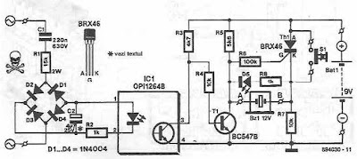
Using this schematic is created a network voltage indicator electronic circuit. If the input voltage is gift across the network, the optocoupler transistor is open, T1 is blocked and controlled rectifier, Th1, is in a very state of conduction. Since each terminals of the piezoelectric buzzer is at identical potential, buzzer is off. If voltage disappears, the transistor T1 enters the conduction and therefore makes the terminal of buzzer to be placed on the bottom (maintains thyristor conduction state). during this state of affairs, there's a sufficiently giant potential distinction across the buzzer and D5's to see that these 2 components to point AC power loss, each audible and visual. By pressing the reset button current is interrupted by Th1, therefore thyristor enter in blocking state and therefore the different terminal of the buzzer is connected to ground. Sourced by: circuitsstream

Automobile White crystal rectifier lightweight Circuit Diagram

Image
Without any dedicated buck converter/white crystal rectifier driver IC, you'll safely drive several customary Hi-efficient white crystal rectifier modules victimization the battery power out there in cars. Here may be a safe and easy white crystal rectifier driver designed for 12V cars. In the Automobile White crystal rectifier wiring, fastened transformer IC1 (7805) provides a gentle voltage of 5V across C2. Resistors R1 limits the present flow through the white crystal rectifier D1 (3v6/350mA) with the assistance of semiconductor T1 (and T2), i.e. parts R1, T1 (and T2) offer a relentless current to D1. Use a decent sink for T1. This crystal rectifier unit offers a relentless lightweight output for input voltages starting from eight to eighteen volts! Auto White LED Circuit Schematic