SP Network Voltage Indicator
Using this schematic is created a network voltage indicator electronic circuit. If the input voltage is gift across the network, the optocoupler transistor is open, T1 is blocked and controlled rectifier, Th1, is in a very state of conduction. Since each terminals of the piezoelectric buzzer is at identical potential, buzzer is off. If voltage disappears, the transistor T1 enters the conduction and therefore makes the terminal of buzzer to be placed on the bottom (maintains thyristor conduction state).
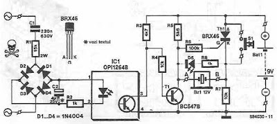
during this state of affairs, there's a sufficiently giant potential distinction across the buzzer and D5's to see that these 2 components to point AC power loss, each audible and visual. By pressing the reset button current is interrupted by Th1, therefore thyristor enter in blocking state and therefore the different terminal of the buzzer is connected to ground.
Sourced by: circuitsstream


Comments
Post a Comment