Posts

Showing posts from April, 2017

Simple 8 Channel DTMF Link Encoder

Image
Generated millions of times every day by our telephone keypads, the eight DTMF frequencies were chosen so that the harmonics and intermodulation do not generate significant in-band signal levels. The signal is encoded as a pair of sine waves, ensuring that no frequency is a multiple of the other and the sum and difference between two frequencies does not match any single tone and that’s why DTMF sounds so ugly!T he DTMF encoder circuit show n here is based on the HT9200B tone generator device produced by Holtek and distributed by Futurlec  among others. The encoder is complemented by a decoder elsew her e in this publication. 8-Channel DTMF : Encoder Schematic The HT2900B is supplied as a nice old fashioned 14-pin device. It can be instructed by a microcontroller to generate 16 dual tones and (in serial mode only) 8 single tones from the DTMF pin output . It s 8 - pin ‘ younger brother’ the HT9200A provides a serial mode only whereas the HT9200B contains a select-able serial/parall...

Simple Auto Tachometer Circuit Diagram

Image
This is the Simple Auto Tachometer Circuit Diagram. Anyone performing their own automobile tune-ups knows how important it is to know your engines speed. With this tachometer, you can measure your engines speed without any connections or annoying timing lights.   Simple Auto Tachometer Circuit Diagram  PC board layout and parts placement Notes Calibrate the unit as folows: a.    Set up this circuit:    Turn on the Tach and allow a few minutes for temperature stabilization. Set S2 to 4 cylinders and adjust R5 for a meter indication of 180 (1800 rpm). Set S2 to 6 cylinders and adjust R6 for a meter indication of 120 (1200 rpm). Set S2 to 8 cylinders and adjust R7 for a meter indication of 90 (900 rpm). To use the Tach, turn it on and let it sit for one minute to allow for temperature stabilization. Extend the antenna, select the right number of cylinders and hold the unit over the engine. If the reading is erratic or the needle jumps around, move th...

1 6 Watt intregated circuit audio amplifier

Image
This Circut based on IC TDA7231 , Minimum voltage require 2 Volts and maximum voltage 15 volts . I recomended voltage is 12 volt DC. Power output 1,6 Watt with 4 Ohm impedance. See audio amplifier with IC TDA7231 below :

iPod and the Auto Sound System

Image
The iPod story seems to be that of a charmed life. If you haven't taken a look around there are all kinds of devices and accessories that are created in order to use right along with the wildly popular and successful iPod product offered by Apple. In fact, I can't think of a better coup for Apple to have pulled off against the giant PC industry, even Microsoft's new product the Zune is having a great deal of difficulty even catching up to the sales that iPod seems to have no trouble garnering. The success is something that may define explanation but could have a great deal to do with the equally popular accessories and adornments that are made for each and every iPod product. You might be wondering exactly what this has to do with auto sound systems but those are just another of the many great iPod accessories that can be found in the market place of today. Seriously! Even some car manufacturers are having upgrades that include iPod adapters that allow drivers to play music...

LED as a diode Rectifier Circuit Diagram

Image
This is a simple LED as a diode Rectifier Circuit Diagram. In certain situations where the current is not high, we can use the famous LED (LED) and diode rectifier voltage power circuits. The LED can be used without problem in a rectification circuit, and also works in the power ratings. Pay attention not to exceed the maximum current of the LED in a wave rectifier.  Using LED as a diode Rectifier Circuit Diagram

SP Network Voltage Indicator

Image
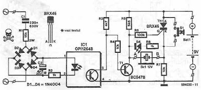
Using this schematic is created a network voltage indicator electronic circuit. If the input voltage is gift across the network, the optocoupler transistor is open, T1 is blocked and controlled rectifier, Th1, is in a very state of conduction. Since each terminals of the piezoelectric buzzer is at identical potential, buzzer is off. If voltage disappears, the transistor T1 enters the conduction and therefore makes the terminal of buzzer to be placed on the bottom (maintains thyristor conduction state). during this state of affairs, there's a sufficiently giant potential distinction across the buzzer and D5's to see that these 2 components to point AC power loss, each audible and visual. By pressing the reset button current is interrupted by Th1, therefore thyristor enter in blocking state and therefore the different terminal of the buzzer is connected to ground. Sourced by: circuitsstream

Automobile White crystal rectifier lightweight Circuit Diagram

Image
Without any dedicated buck converter/white crystal rectifier driver IC, you'll safely drive several customary Hi-efficient white crystal rectifier modules victimization the battery power out there in cars. Here may be a safe and easy white crystal rectifier driver designed for 12V cars. In the Automobile White crystal rectifier wiring, fastened transformer IC1 (7805) provides a gentle voltage of 5V across C2. Resistors R1 limits the present flow through the white crystal rectifier D1 (3v6/350mA) with the assistance of semiconductor T1 (and T2), i.e. parts R1, T1 (and T2) offer a relentless current to D1. Use a decent sink for T1. This crystal rectifier unit offers a relentless lightweight output for input voltages starting from eight to eighteen volts! Auto White LED Circuit Schematic

How to Select the Right VFD Inverter or AC Motor Drive

Image
The choice of the right AC motor drive (VFD) for the application is very important and has great influence on its lifetime. If the capacity of AC motor drive is too large, it cannot offer complete protection to the motor and motor maybe damaged. If the capacity of AC motor drive is too small, it cannot offer the required performance and the AC motor drive maybe damaged due to overloading. But by simply selecting the AC motor drive of the same capacity as the motor, user application requirements cannot be met completely. Therefore, a designer should consider all the conditions, including load type, load speed, load characteristic, operation method, rated output, rated speed, power and the change of load capacity . The following table lists the factors you need to consider, depending on your requirements. Selection Note for VFD Why to use Choke for VFD? When the AC Motor Drive (VFD) is connected directly to a large-capacity power transformer (600kVA or above) or when a phase lead cap...

Data accretion System Circuit Diagram

Image
In this circuit, an HA-4900 series comparator is used in conjunction with a D/A converter to form a simple, Data accretion System Circuit Diagram versatile, multichannel analog input for a data acquisition system. The processor first sends an address to the D/A, then the processor reads the digital word generated by the comparator outputs, lb perform a simple comparison, the processor sets the D/A to a given reference level, then examines one or more comparator outputs to determine if the inputs are above or below the reference. A window comparison consists of two such cycles with two reference levels set by the D/A. One way to digitize the inputs would be for the processor to increment the D/A in steps. The D/A address, as each comparator switches, is the digitized level of the input. While stairstepping, the D/A is slower than successive approximation; all channels are digitized during one staircase ramp.

General Purpose Oscillator

Image
The oscillator shown in Figure1 is frequently used in digital circuits and may, therefore, look very familiar. Many readers may not know that this type of oscillator suffers from a nasty draw-back caused by noise. When the amplitude of the noise is higher than the hysteresis of the gates used for the oscillator, spurious switching pulses are generated near the zero crossings. This problem can be cured only by ensuring that the rise time of the input signal is shorter than the reaction time of the relevant gate. When the oscillator is built with fast logic gates, such as those in the HC-series, the like-lihood of the problem occurring is great. However, as long as the positive feedback is fast enough, nothing untoward will happen. However, when delays occur owing to the transit time of the components used, the problem may rear its head. In the configuration of Figure 1a , the signal passes through two inverters and thus experiences twice the transit time of a single gate. The upper sig...

Solid State Relay Required Only 50uA Drive Current

Image
This circuit demands a control current that is 100 times smaller than that needed by a typical optically isolated solid state relays. It is ideal for battery-powered systems. Using a combination of a high current TRIAC and a very sensitive low current SCR, the circuit can control about 600 watts of power to load while providing full isolation and transient protection. Sourced by :link

SIMPLE RF REMOTE SWITCH CIRCUIT

Image
SIMPLE RADIO FREQUENCY REMOTE SWITCHING CIRCUIT RF TRANSMITTER SECTION Today we are going to discuss about the simple RF (Radio Frequency) Transmitter and Receiver circuit. RF(Radio Frequency) is a High Frequency signal commonly used for communication applications, due to its high frequency we can transmit signal to a sufficient distance (about 300 Foots) without attenuation. Here, the simple RF switching circuit is used to turn ON and turn OFF an LED (For Demonstration) you can replace the LED with a switching RELAY and control any appliances. Read More.....

Fan and Air Conditioner Control Switch

Image
The circuit consists of power supply and control sections. The power supply section is built around transformer X1, bridge rectifier BR1 and filter capacitor C1. The 50Hz, 230V AC mains is stepped down by transformer X1 to deliver a secondary output of 9V, 300 mA. The transformer output is rectified by the bridge rectifier and filtered by capacitor C1. Fan and Air-Conditioner Control Switch circuit Diagram When the mains is switched on for the first time, pin 3 of IC CD4017 (IC1) goes high and relay RL1 energises to switch on the fan. When mains is briefly switched off using S1 and then switched on, the power to IC1 is maintained by the charge on capacitor C1. At the same time, there is a trigger pulse on the clock input (pin 14) of IC1, which advances the decade counter and relay RL2 energises to switch-on the air-conditioner. Both the air-conditioner and the fan will be turned off if the switch is in the ‘off’ position. Assemble the circuit on a general-purpose PCB and enclose in a s...

Modular Phono Preamplifier

Image
High Quality Moving Magnet Pick-up module, Two-stage Series/Shunt feedback RIAA equalization Any electronics amateur still in possess of a collection of vinyl recordings and aiming at a high quality reproduction should build this preamp and add it to the Modular Preamplifier chain. This circuit features a very high input overload capability, very low distortion and accurate reproduction of the RIAA equalization curve, thanks to a two-stage op-amp circuitry in which the RIAA equalization network was split in two halves: an input stage (IC1A) wired in a series feedback configuration, implementing the bass-boost part of the RIAA equalization curve and a second stage, implementing the treble-cut part of the curve by means of a second op-amp (IC2A) wired in the shunt feedback configuration.  . This module comprises also an independent dual rail power supply identical to that described in the Modular Preamplifier Control Center. As with the other modules of this series, each electronic b...

A signal amplifier module for HF

Image
In building QRP HF radios, having an RF signal level amplifier building block is handy. You want 50 Ohm output impedance, some reasonable gain, supply voltage of the usual 10-14V and ease of building using standard parts from your parts bin. Some searching around the interwebs came up with a good idea for circuit from Aaron Parks, KC8FQD, who did a YouTube video on a WWV receiver. [ ]

Simpled Solar Powered Lithium Ion Battery Charger Circuit

Image
The circuit below feeds a controlled current and voltage to a 3.6v lithium ion battery. The current is limited to 300ma and the voltage is limited to 4.2 volts. The circuit uses a LTC1734 IC from Linear Technology. No diode is needed between the circuit and a 6 volt solar panel. Some very nice 6 volt solar panels are available from www.plastecs.comTheir SP6-200-12 cranks out about 1 watt while the SP6-300-12 can produce about 2 watts. Assuming a 6 hour sunlit day, the 2 watt panel will pump about 1.8 amp-hours into a battery.

Creating receiving managing program notifications October 2008

System is processing data Please download to view '; $(document).ready(function() { $('#embed_size, #embed_start').change(function(){ $size_embed = $('#embed_size').val().split("x");; $reader_embed2 = $reader_embed.replace(".html", ".html?t={number}"); $reader_embed2 = $reader_embed2.replace("{width}", $size_embed[0]); $reader_embed2 = $reader_embed2.replace("{height}", $size_embed[1]); $reader_embed2 = $reader_embed2.replace("{number}", $('#embed_start').val() ); $("#embed_text").val($reader_embed2); }); });

AOC LCD MONITOR AOC 919V AOC A240WD SMPS Circuit Diagram

Image
AOC 19 inch and 24 inch LCD Monitors - Power Supply and LVDS Circuit Diagram 19" TV SMPS - 715G2824-2-2 AOC 919V - Power Supply [SMPS] Circuit diagram ( 715G2824-2-2) Scaler AOC A240WD - SMPS [power supply] Circuit diagram Click on the schematics to zoom in

Simple 8 Random Flashing LEDs

Image
This project flashes eight LEDs in an apparently random manner. It uses a 4060 combined counter and display driver IC which is designed for driving 7-segment LED displays.  Circuit diagram : Simple 8 Random Flashing LEDs The sequence is not really random because seven of the LEDs would normally be the display segments, the eighth LED is driven by an output that is normally used for driving further counters. The table below shows the sequence for the LEDs. You can use less than eight LEDs if you wish and the table may help you decide which ones to use for your purpose.

Simple Analog to Digital Converter with LT1018

Image
This is a Simple Analog-to-Digital Converter with LT1018. An analog-to-digital converter (abbreviated ADC, A/D or A to D) is a device that converts a continuous physical quantity (usually voltage) to a digital number that represents the quantity's amplitude.The converter has a 60-ms conversion consumes 460 pA of 1's. 5 V power supply and maintains an accuracy of 10 bits on a 15 ° C in the temperature range of 35 ° C.   Simple Analog-to-Digital Converter with LT1018 Circuit Diagram A pulse applied to convert the command line causes Q3, operating in reverse mode, the discharge path through the diode 10 kO, forcing its collector low. Q3 results of reverse mode switching in a capacitor discharge to 1 mV of ground. During the time of the ramp value is less than the input voltage, output of the CIA is low.  This allows pulses ClB stabilized quartz oscillator, modulating Q4. The output data appears at the collector of Q4. When the ramp crosses the starting value of the output ...

Simple 12V To 24V DC DC Converter Circuit Diagram

Image
his is the Simple 12V To 24V DC-DC Converter Circuit Diagram. This simple DC-DC converter can provide up to 24V from a 12V source. It can be used to run radios, small lights, relays, horns and other 24V accessories from a 12V vehicle with a maximum draw of about 800mA.   Simple 12V To 24V DC-DC Converter Circuit Diagram It can be used to charge one 12V battery from another, or step up the voltage just enough to provide necessary overhead for a 12V linear regulator. Using one op-amp as a squarewave oscillator to ring an inductor and another op-amp in a feedback loop, it won't drift around under varying loads, providing a stable 24V source for many applications. With a wide adjustment in output this circuit has many uses. 

Simple Bar Display With Alarm Flasher Schematic

Image
Hello Freinds ! Here designed SIMPLE BAR DISPLAY WITH ALARM FLASHER . Schematic: Return to Display Circuits. By using two switching transistors and two LEDs, this circuit can distinguish low-level ac and dc signals. If the red LED illuminates, the signal is positive dc. If the yellow LED lights, the signal is negative dc. If the signal is ac, both LEDs will light. Bar Display With Alarm Flasher Circuit Schematic

WiFi Controlled Robotic Vehicle Electronic Project Abstract

             This project is a robot vehicle that can be controlled through any computer wirelessly using a WiFi link. It transmits real-time video to the controlling computer using the same link. The video transmitting camera mounted on it. It also has obstacle detection,temperature,sound and light sensitivity feature.           Usually robots are controlled through a laptop using an WiFi link which is subject to attenuation, noise and has a very limited range as well. This project features a robot that uses WiFi 802.11G standard for its control signals through TCP/IP protocol, which has flow control. This enables uninterrupted and reliable transmission of control signal to the robot vehicle. WiFi support high data rates which enables good quality uninterrupted video transmission from the robot to the computer. Image capturing is done by mounting an IP-camera over the Robotic Car. Obstacle detection is done...

Elco tester circuit

Image
Elco testing small to use AVO meters. But to distinguish between the elco elco 20.000uF/50V 2200uF/50V size would be very difficult, perhaps this phenomenon that makes creative hands itch to make elco with two label values. Scheme tool as follows, do not smile once, indeed simple. The cost to make it too cheap, not up to $ 1. Elco tester circuit The workings of this tool based on the nature of the condenser, the condenser ability to store electrons / voltage. Since each condenser has the characteristic charging time and discharging time is different for each size and type dielektrika. Ideally, the larger size, the greater the time required for charging and discharging (charging and disposal charges). How to use : Make sure the position of the switch (SW1) on the discharging position (position A). Connect / elco pairs that will be tested, then empty the contents briefly elco by pressing SW2 (approximately 1 to 3 seconds). Position the switch in the charging position (position B), the LE...